Phase Shifts in RC Filters
A tutorial on the phase shift of a single pole RC filter (and a quick lesson on the polar form of complex numbers).
The impedance of a capacitor of value C is represented by
The impedance of a capacitor of value C is represented by
Where w is equal to 
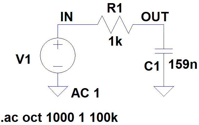
Therefore the transfer function of the low pass filter the circuit below is
Therefore the transfer function of the low pass filter the circuit below is

which equals
If plotted on a graph, all j terms (imaginary terms) represent an excursion along the y axis and all non j terms (real terms) represent an excursion along the x axis. Positive values of j go UP the y axis and negative values of j go DOWN the y axis. Positive and negative real values go right and left along the x axis. By picturing the real and imaginary number on the x and y axes, it is easy to convert a complex number into its polar form and hence determine the phase shift of the circuit.
The polar form of a complex number can be found by determining the magnitude of the complex number and the angle between the real and imaginary parts.
Thus a complex number of 10 + j35 has a polar form of magnitude
or
Likewise a complex number of 7 – j12 has a polar form of
If a fraction has a complex number on the numerator and on the denominator, simply divide the denominator magnitude into the numerator magnitude and subtract the denominator angle from the numerator angle.
Thus
It can also be seen that if the numerator has no imaginary term (
The phase shift of the RC circuit above can be evaluated at any frequency by replacing the w term with
For the circuit above, the transfer function is
So at a frequency of, say, 100Hz, this has a transfer function of
which has a polar form of
So we can see that at 100Hz, the output is 0.995 times the input and we have a phase lag of 5.7°.
Likewise at a frequency of 10kHz, the polar form of the transfer function is
Indeed we can see that for a single order filter, at frequencies of less than 1/10th of the break frequency, the phase shift is nearly zero and for frequencies of higher than 10x the break frequency the phase shift is nearly 90 degrees. Although we are 5 degrees out, this is a good enough approximation for most applications.
At the break frequency the real and imaginary terms are equal so the angle between the real and imaginary terms is 45 degrees.
Sitemap: www.simonbramble.co.uk/sitemap
© Copyright Simon Bramble